

How I Bypassed GE’s Fancy Software with virtual Jumper Wires
TLDR; GE’s PLC logic forces outputs on the Digital Output modules that are not in use in order to block other logic running on the same PLC. I bypassed it using virtual IO module and a custom software running on the PLC to spoof the signal of a windvane and control the turbines wake steering.
Our story begins with an idea. Can a wind turbines wake reduce the power output of a wind turbine behind it?
 https://www.empireengineering.co.uk/exploring-wake-losses-in-offshore-wind/
According to researchers at the National Research Energy Labs (NREL), it could. It could have an effect of up to 14%, according to the paper we published in 2019. My contribution to the seminole study was very trivial. In fact I didn’t even know it was being crafted at the time. My job was to deliver the engineering solution and the data needed for the study. A much more straightforward thing to achieve for an engineer with little knowledge of the science at the time. My goal was to somehow make it possible to steer the wake of one turbine around the face of the other.
My Brilliant Boss
He used a tiny plastic novelty wind turbine model he had on his desk, and a pencil. He propped them up and explained how wake steering works. After the hand waving, he leaned back on his squeaky office chair, and took a look outside of his window. He stared into the empty parking lot and pieced together his plan to use the wind vane to hijack the controls of a multi-million dollar piece of machinery.
The problem is that GE didn’t want anyone messing around with the controls alogirthm that they worked so hard on to build. It was designed to follow the optimal wind direction to output the most power the turbine can. And for sure, trying to reprogram it would void the warranty on the equipment. So instead the answer must be to trick the wind vane sensor that the optimal direction the wind is coming from is not where it thinks it is. This was obvious to my Boss because he saw wind turbines in the past steering all over the place when the wind vane was damaged.
So Now What?
The same model wind vane was installed on most of the GE wind turbines.
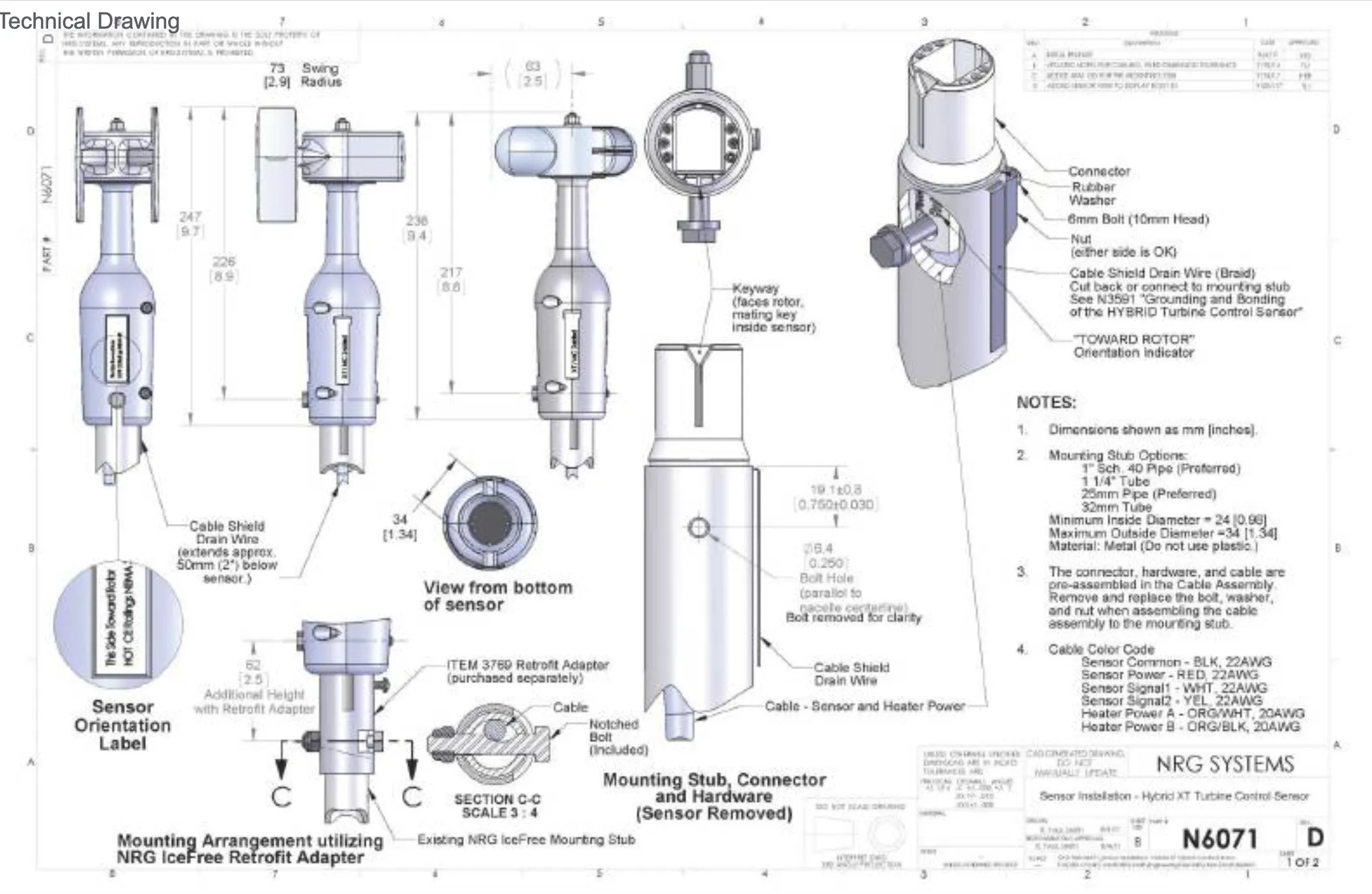 Hybrid XT Push-Pull Vane
The specific model was the Hybrid XT Push-Pull Vane. This meant that I had two cables from the wind vane (Yellow, White) that send a degree signal to the GE control software.
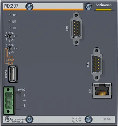
The wires are inserted into a digital input module on the Bachmann Process PLC installed on the GE ESS wind turbines. For a full list of parts on a GE ESS wind turbine see here.
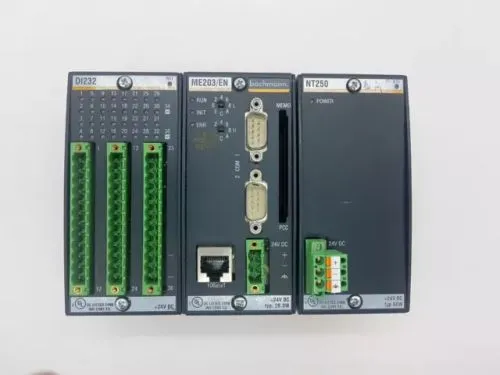 Bachmann PLC with a Digital Input Module
Wind Vane Details
The Model 7894 Push-Pull Hybrid XT Vane is designed as a direct replacement for IceFree™3 wind vanes, compatible with NPN and PNP controllers. It provides two output signals in push-pull format, allowing current sourcing and sinking for wide compatibility.
 Wind Vane Dithering Control
https://www.manualslib.com/manual/1639611/Nrg-Systems-Hybrid-Xt-Vane.html?page=25#manual
Wind Vane Dithering Control
https://www.manualslib.com/manual/1639611/Nrg-Systems-Hybrid-Xt-Vane.html?page=25#manual
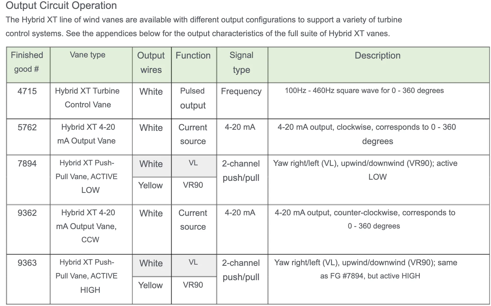
Output signals:
• Yaw Right / Yaw Left (VL) → White wire
• Upwind / Downwind (VR90) → Yellow wire
Most wind vanes are under-damped, causing them to move erratically due to turbulence. Some turbine control systems rely on this motion (dithering) to estimate the average wind direction by measuring the time spent in left vs. right positions. The Model 7894 XT vane has a stable output, reducing erratic movements and improving wind direction tracking. It generates a compatible dithered signal for controllers that require dithering.
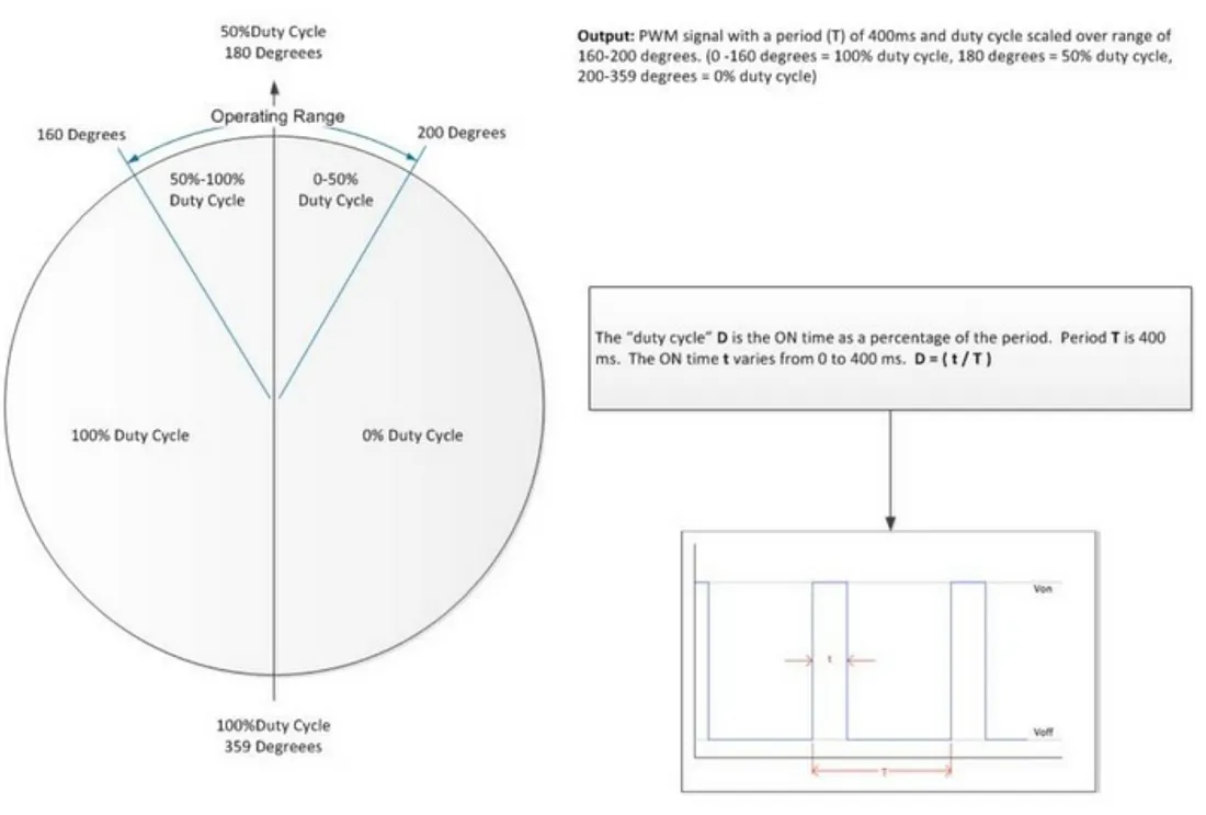
The duty cycle of the PWM output signal is used to indicate wind direction:
• 0–160 degrees → 100% duty cycle
• 180 degrees → 50% duty cycle
• 200–359 degrees → 0% duty cycle
When the vane detects correct wind alignment, the output duty cycle stabilizes. This method is more accurate and a stable tracking of wind direction compared to under-damped sensors.
What About the Controller?
So even though I have these signal wires I still need to be able to somehow spoof them. The key here lied in a clever idea. I cant take all of the credit to be honest. I was in Boston sitting in a training session with an instructor that was going over the details of the Bachmann PLC.
After trying out a very European coffee from a European break room, with some very polite germans I returned back to the conference room. The 5 day training was held in the Boston branch office no the Bachmman headquarters in germany. Either way they had a very talented developer explain the intricate layers of control and flexibility the Bachmann PLC has. He mentioned the debugging capabilities and even a very interesting feature that allowed a user to simulate IO’s in real time.
I asked, “Can I create a virtual IO card that looks like a real signal to the software?”. With a very matter of fact look on his face he mentioned that it is designed to mimic a real IO device, and as far as the software is concerned it is a real signal from an external sensor. I then went on to ask details about spoofing signals, and how I could use a configuration file to boot up the virtual IO.
After testing, and troubleshooting on a local PLC at my desk I was able to spoof a signal. I made sure that the inputs expected by GE software running on the Bachmann PLC came from a virtual input module, I did this by changing the module ID of the real module and assigning the ID to the virtual module. The next step was to create another piece of software that ran on the Bachmann PLC alongside the GE Software. This code would pass all the inputs from the physical module to the GE Software by feeding the physical inputs to the virtual input module. I tested the software and made sure that it would boot up and wouldn’t cause any issues with the GE Software. Finally, I edited my program to modify the two inputs from the wind vane by adjusting the VR90/VL values so that the final output would provide a wind direction offset in the amount I desired.
Final Steps
To put it all together I had to create an installation script that did the following:
• Connect to Bachmann PLC
• Add/Configure a virtual IO
• Swap ID of Digital Input Module, and Virtual Module
• Install “Custom Wake Steering ByPass” software program
• Start up the “Custom Wake Steering ByPass”
• Save settings and reboot the Bachmann PLC
I wrote the script as a batch file that could run through a list of IP addresses at the Site (Wind Turbine IP addresses), and establish a SSH terminal with the PLC. I completed the steps using terminal commands defined by Bachmann’s operator terminal menu. I then initiated file transfers for the “Custom Wake Steering ByPass” program installation. Finally the changes are saved and a reboot is issued. I also created a step where I checked it was running once the PLC booted back up.

Let’s Build the Future, Together
At SCADADOG, we believe innovation thrives on collaboration. We’re not just creating solutions—we’re
shaping industries and driving digital transformation. Ready to join us on this journey?
✨ Innovate with Confidence. Grow Without Limits.